A novel no-moving-parts sensor for detection of eye fixation using polarized light and retinal birefringence information
For a more detailed version of this research report, please read the following publication:
Gramatikov, B.I., Guyton, D.L. A no-moving-parts sensor for the detection of eye fixation using polarised light and retinal birefringence information. Journal of Medical Engineering & Technology (Taylor & Francis), 41, No.4, pp.249-256. Published online: 26 Jan 2017; DOI: 10.1080/03091902.2017.1281357.
https://www.ncbi.nlm.nih.gov/pubmed/28122478
http://www.tandfonline.com/doi/full/10.1080/03091902.2017.1281357
http://www.tandfonline.com/doi/pdf/10.1080/03091902.2017.1281357
http://dx.doi.org/10.1080/03091902.2017.1281357
http://www.tandfonline.com/eprint/BgVSDatrdRUTXdZc2qzG/full
There is an increasing demand for accurate portable eye trackers and fixation monitors. The scope of potential applications is extensive, ranging from medical diagnostics to intuitive and fast computer interfacing.
An eye tracker can calculate precisely where a subject is looking. Since eye gaze is a strong indication for current attention and intention, it is possible to automatically and accurately estimate: where the person is looking, the current and past areas of attention, the possible intentions of the person, and the possible mental state of a person. Eye tracking thus provides a key input to enable a range of applications and devices that would benefit from utilizing such information. The scope of potential applications is extensive, ranging from medical diagnostics to intuitive and fast computer interfacing. Examples include computer interaction in professional environments, clinical diagnostics, security applications, vehicle security and vehicle interaction, computer gaming, etc. Presently, eye tracking already provides great value in commercial and research-related applications such as psychology and vision research, commercial usability and advertising studies, eye-based communication for people with highly limited mobility, etc.
While the purpose of an eye tracker is to identify where a person is looking, most contemporary eye trackers detect eye position, which must be separately calibrated to the actual gaze direction. Eye position detection usually employs the reflection of a point light source from the front of the cornea (corneal light reflex) relative to the bright or dark pupil, or relative to the reflection of the same point light source from the back of the crystalline lens of the eye. Eye position can be estimated by a variety of techniques, each of them having its advantages and limitations [1-9]. Most eye trackers monitor the relative positions of the pupillary image and/or of the Purkinje light reflexes [3, 5, 6, 10, 11]. The most prevalent approach to gaze direction detection with most commercial systems available today appears to be the indirect method of determining corneal light reflex position versus pupil position [10-12].
A potential alternative to eye position estimation is foveal tracking. When an individual looks at a target, that target is imaged on the fovea (the most sensitive part of the retina). It is thus foveal fixation that correlates precisely with gaze direction. Yet, it has not been possible until recently to detect true foveal fixation remotely, continuously, non-invasively and reliably. Recent research has shown that techniques which effectively track or monitor the optical projection of fundus landmarks out from the eye afford a more direct measurement of fixation direction, are physiologically more relevant, and can achieve high precision. It has also been shown that landmarks such as the fovea and the optic disc can be detected robustly by measuring the amount of polarization change that the surrounding birefringent nerve fibers cause during double passage of a beam of polarized light through them upon fundus reflection in double-pass systems.
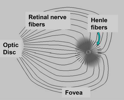
Figure 1 The fovea, the optic disc, and the birefringent retinal nerve fibers and Henle fibers. Shown is also the Haidinger brush centered around the fovea, seen subjectively in linearly polarized light and caused by the directionally-sensitive light absorption caused by the dichroism of the lutein pigment crystals arrayed along the radially-oriented Henle fibers.
Polarized near-infrared light is reflected from the foveal and optic disc areas in bow-tie or propeller patterns of polarization states, as shown in figure 1. The propeller patterns are due to the property of the small diameter neurotubules coursing along the retinal nerve fibers to change the polarization state of light (“form” birefringence). In the foveal area this pattern of polarization states is caused by the neurotubules in the radially displayed Henle fibers, with the resulting propeller pattern similar in shape to the visible Haidinger brush phenomenon [18]. Such patterns are of constant shape, size, and location, for a given type of polarized light entering the eye, and are therefore detectable by polarization analysis, offering the opportunity for eye tracking. The major advantage of this new eye-fixation detection and tracking method is that it uses true information coming directly from retinal landmarks, to identify the direction of foveal gaze, as opposed to existing eye-tracking systems which use reflections from other structures to indirectly estimate the direction of foveal gaze. Historically, human foveal birefringence was measured in vivo with Mueller-matrix ellipsometry in the late 1980s [19]. In the early 1990s, the birefringence of the retinal nerve fibers was utilized by Dreher et al. [20] to measure the thickness of the nerve fiber layer. Bow-tie patterns, typically seen in birefringence images of the macula, have also been used for different diagnostic purposes [21, 22]. Guyton and colleagues reasoned that the birefringence of the nerve fibers surrounding the human fovea might be used to detect the strict radial geometry of the Henle fibers, and thus locate the fovea. Such a technique was developed by our group to monitor foveal fixation [23-25] and to detect proper alignment of the two eyes in infants and young children [26-33] for the purpose of vision screening and early detection of strabismus, often with attendant amblyopia. A similar device was developed and successfully used for identification of patients with ADHD [34]. In the meantime it became known that central fixation may last for only very short episodes [35, 36], which puts additional requirements on the scanning speed, and on the scanning motors in particular.
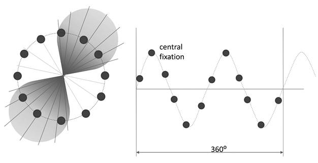
Figure 2 Scanning around the fovea produces a signal. The signal is a sine wave whose frequency helps identify the position of the fovea. With central fixation, the sine wave has a frequency twice the scanning frequency. This frequency doubling disappears with para-central fixation. This method helps detect central fixation in monocular systems and eye alignment in binocular systems.
Using the eye in an auto-conjugate arrangement, these first instruments employed a circular scanning system. When the eye was focused on the intended fixation point (a light source in the center of the circular scan), the light reflected from the retinal scan would be automatically focused by the eye back to the source, where it could be deflected by a beamsplitter and measured for changes in polarization state induced by double passage through the Henle fibers. With central fixation, because the scanning path was a circle centered around the center of the foveal bow-tie, the polarization state of the light changed at twice the frequency of the scan, 2f (figure 2) With paracentral fixation, however, the change in the polarization state was only at the frequency of the scan f [23, 24]. This method helped detect central fixation in a monocular system and eye alignment with a binocular system. The rapidly spinning motor, however, added noise and vibration, and was generally of limited life. To avoid these problems, we developed a no-moving-parts eye fixation monitor. Instead of circular scanning, this instrument utilized four spots of linearly polarized light to obtain spatial information about the position of the bow-tie. With central fixation, two spots were aligned with the “bright” arms, and two were aligned with the “dark” arms of the bow-tie pattern of polarization states surrounding the fovea. In figure 2 these spots were the two circles in the middle of each leaf of the bow-tie (spots/sensors A and B), and two circles in the middle of each of the pale areas between the leaves (spots/sensors C and D). The light reflected from the fundus traveled through a quarter wave plate, a polarizer, and onto a quadrant photodetector. After amplification and digitization, the signals from the four photodetectors were combined into a normalized differential signal
ND = (A+B-C-D) / (A+B+C+D) (1)
that discriminates between central fixation and the lack thereof. At central fixation, ND reaches its global maximum, which allows it to be used in conjunction with a threshold for detecting central fixation [37]. The same quadrant detector was used to obtain four signals used for foveal eye tracking [38] . This system delivered the gaze coordinates directly from the four measured signals A, B, C and D :
[x,y] = [ A B C D ] * V (2)
where V is a 2x4 transformation matrix that can be calculated preliminarily after calibration measurements. Both systems suffered from three major disadvantages, though: a) the four spots of light were projected onto the foveal region simultaneously, rather than sequentially, which increased the noise, b) the orientation and intensity of the propeller shape affected by the corneal birefringence, which varies from patient-to-patient, and c) the number of sensors with the quadrant detector is limited to four, which affects the precision of scanning. Ideally, the scanning can be achieved by a higher number of detectors, arranged in a certain pattern, i.e. circular as shown on figure 2, that also integrates emitters.
The idea of interrogating spots on the retina with no-moving-part transducers
The ultimate goal is to develop an eye tracking and gaze fixation detection system that includes an electronically scanned optical illumination system which emits polarized near-infrared (NIR) light to a retina in an eye of a subject, and an optical detection system arranged in an optical path of the NIR light after being reflected from the retina of the eye of the subject, coinciding with the illumination system. The system will therefore consist of a number of optical transducers (emitter/detectors), each one interrogating a certain spot on the retina in the vicinity of the fovea, and possibly the optic disc, thus eliminating the requirement for scanning systems with moving parts. Figure 3 shows the principle of interrogating a spot on the retina by means of an optical transducer using a holed sensor. Light emitted through the hole is focused by the eye’s own optics onto a spot on the retina that corresponds to the position of the transducer with respect to the eye. In a complete double-pass configuration, much of the returning light is captured by the photodetector (sensor) surrounding the central hole. Each time an emitter is flashed, light of changed polarization is reflected by the corresponding foveal region and is measured by the sensor. The goal of this work was to develop and test one such transducer, and to assess its applicability to eye tracking and eye fixation tasks in a multi-transducer setting.
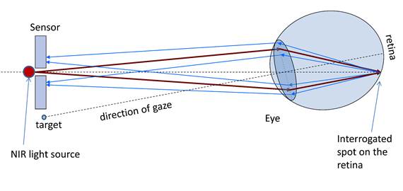
Figure 3 Interrogating spots on the retina by means of an optical transducer. Near infrared (NIR) light emitted through the central hole in the sensor is focused by the eye’s own optics onto a spot on the retina that corresponds to the position of the transducer in the visual field of the eye. In a complete double-pass configuration, much of the returning light is captured by the sensor surrounding the central hole.
The polarization-sensitive optical transducer
Figure 4 shows such a polarization-sensitive optical transducer, comprising a coaxial emitter/detector sensor, developed specially for the purpose. The transducer is positioned at 40 cm from the eye, and consists of a solid state low power laser diode LD, a polarizer P, a filter F, and a photodetector S. The 35 mW diode laser (Hitachi HL7859MG), driven by a laser diode driver FL500 (Wavelength Electronics), emits 780 nm linearly polarized light (in our case vertically oriented), which is focused by the eye’s own lens onto a spot on the retina, and is back-reflected toward the transducer, in a double-pass manner. In its receiving part, the NIR laser line filter F (Thorlabs, FL05780-10, of central wavelength 780 nm, FWHM = 10 nm) eliminates all wavelengths except for a narrow window about 780 nm. Since the polarization state of light has changed from linear to elliptical, the linear polarizer P (Meadowlark Optics, dichroic sheet polarizer DP-050-NIR1) is used as an analyzer, to transmit only one linear component of the polarization, for example the vertical component or the horizontal component. A 1.5 mm center hole was punched in the polarizer, to pass the initial laser light. The difference (horizontal – vertical) of the two orthogonal components represents the S1 element of the Stokes vector S = {S0 S1 S2 S3} that describes fully the polarization state of light [39]. In our setup, the polarizer was oriented horizontally, in order to detect the horizontal component, which would essentially represent the deviation from the initial vertical polarization. In most polarimeters, as well as in our moving part systems, both orthogonal polarization components are utilized, to fully characterize S1 (differential measurement). Yet this requires a more complex optical configuration (usually involving a polarizing beamsplitter) which would be inconsistent with our goal of a compact transducer. The single horizontal-component-based receiving system has proven to work reliably after some optimization [31, 33]. Finally, the ceramic photodetector S (Thorlabs, FDS1010, 350-1100 nm) detects the light transmitted by the polarizer, except for the very central ray. A 1 mm central hole was drilled in the photodetector using a diamond drill. In another photodetector, we had the hole custom produced by Laserage Technology Corporation, using laser drilling (the process of repeatedly pulsing focused laser energy at a material, vaporizing layer by layer until a thru-hole is created: a fast process that is ideal for high production volumes). The returning light is slightly defocused, and is largely captured by the surface of the photodetector surrounding the laser source. Thus the polarization-sensitive optical transducer provides information about the polarization change that has occurred at the interrogated spot on the retina. The signal from the photodetector is further amplified by a low-noise DC amplifier and is then digitized by a 16-bit analog-to-digital (A/D) converter. No low-pass filtering was used in this setup.
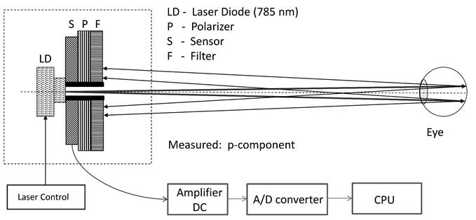
Figure 4 The polarization-sensitive transducer, capable of interrogating a single point on the retina in the vicinity of the fovea.
Laser safety
The laser is driven by the FL 500 laser diode driver (Wavelength Electronics), in constant current (CC) mode. The transducer and the measurement setup adhered strictly to the American National Standard for Safe Use of Lasers [40]. Theoretical considerations and experimental measurements show that a 35 mW laser delivers less than 0.14 mW/cm2 at a distance of 40 cm (where the test subject eyes are placed). For a point source ocular exposure to a laser beam from 700 nm to 1400 nm, the maximum permissible exposure (MPE) for a continuous wave (CW) laser for a duration of 10 to 30,000 s is:
MPE = CA x 10-3 W/cm2 (3)
where the factor CA for the same wavelength range is calculated as CA = 10(0.002(λ-700nm)). Using λ=780 for our laser, we obtain CA =1.45, and hence
MPE = 1.45 mW/cm2 = 1,450 µW/cm2 (4)
Thus the output of the laser of 0.14 mW/cm2 (or 140 µW/cm2) at the subjects' pupil is well below the MPE for the wavelength used, for practically infinite exposure. It is important to note that to provide the most conservative possible calculations, we made the assumption that the laser is stationary. In a scanning system, each laser is usually driven in a pulsed mode and one at a time, thus delivering even less irradiance at the point being interrogated.
Testing the sensor
The sensor was tested on a 16-year old test subject, under a protocol approved by our Institutional Review Board and after obtaining proper consent. To test the signal quality obtainable, using just one sensor, the test subject was asked to fixate successively on twelve “glow-in-the-dark” targets located on a circle around the emitter/detector, in order to simulate the retina being interrogated by twelve sensors placed on a 3° diameter circle surrounding the projection of the fovea (figure 5). A simple test program was written in LabWindows CVI (National Instruments), with a graphical user interface designed to control the laser, the data acquisition, and the archiving of the data.

Figure 5 Interrogating different spots around the fovea by asking the test subject to fixate on different fixation targets, positioned around the optical transducer.
Results
The resulting twelve measurements, taken approximately 10 s apart, were plotted as diamonds in figure 6. They can be considered to be the same as when one would have scanned around the center of the fovea with twelve transducers, used sequentially. The signal obtained is close to the “ideal” sine wave that would have been recorded from an “ideal” propeller-type birefringence pattern from a human fovea presented in figure 2. We deem these results quite satisfactory, considering factors such as imperfect bow-tie, imperfect fixation by the test subject, a relatively low number of scanning positions (12), an imperfect filter and the presence of some residual optical noise.
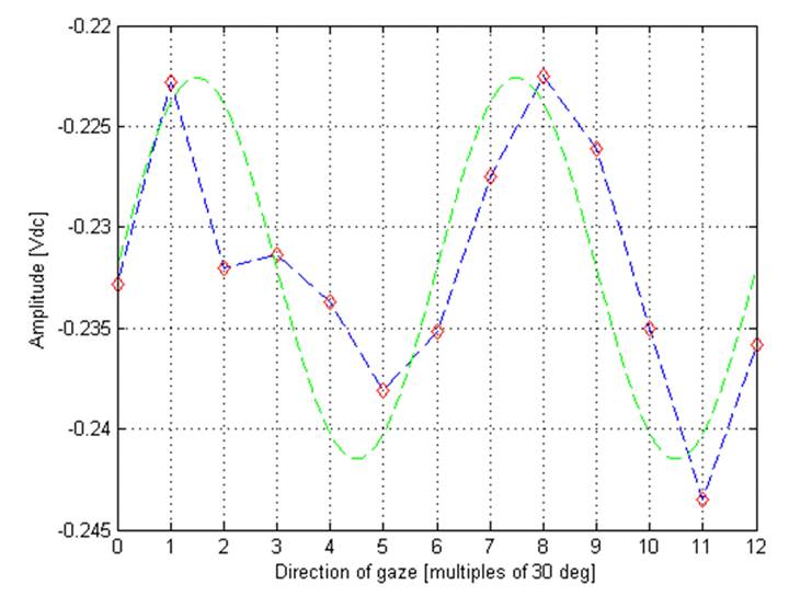
Figure 6 The twelve measurements obtained during fixation on each of the twelve fixation targets. The measurements can be considered to be the same as when one would have scanned around the center of the fovea with twelve transducers, used sequentially. For comparison, the “ideal” sine wave is shown.
Discussion
The described transducer has the distinct advantages of small size and light conservation in comparison with existing optical systems. It can be produced at a low cost, and can be integrated in sensor arrays capable of detecting the position of the fovea without moving parts. This is a significant advantage over use of the precision motors used in retinal scanning systems, which can be costly, noisy, heavy, consume significant power, and are subject to wear and tear. When compared to a circular scanning system that contains only one motor, the cost of 10-12 transducers, even separately, without integration), can be less than the cost of a single precision motor. Similarly, the cost of a 10x10 2D transducer system could be less than the cost of a 2D galvanometer scanning system. A significant advantage would also be the ability to organize the transducers in an arbitrary pattern, rather than in an X-Y raster scan configuration. In addition, because only separate points of the retina are interrogated (rather than a continuous scanning trace), the total light load is significantly reduced, compared with circular or raster scanning systems.
To even better measure polarization changes of the light, and suppress changes induced by birefringence of the cornea, an improved polarization-sensitive emitter-detector may include a holed optimizing retarder in the return path, positioned behind the filter [41]. The retarder can be electrically controllable, for example one of the popular liquid crystal (LC) retarders. It can also be a 90º polarization rotator, typically of the twisted nematic (TN) type. Using a LC/TN polarization rotator allows two orthogonal measurements (s- and p-polarization) to be taken in succession. Subtracting the two measurements yields a highly sensitive differential polarization measurement, as mentioned in subsection 2.2. This arrangement suppresses contamination from reflections from objects where the light is partially depolarized upon reflection, such as from the skin. If in addition the two orthogonal measurements are 45 degrees from the original azimuth of linear polarization, this arrangement also strongly suppresses specular reflections from objects where no change in polarization occurs, such as reflection from the cornea. This concept allows further optimization by choosing a meridional alignment for the entire device to be most immune to the corneal birefringence of the subject whose direction of gaze is being estimated.
A disadvantage of the foveal-birefringence-based systems is the relatively small visual angle that can be analyzed. Due to the relatively small size of the fovea and the bow-tie pattern compared with the whole retina, the system can reliably detect the direction of gaze only within a central area of about 5° diameter. It has been shown [41] that an array of 4x4 or 5x5 transducers can track the direction of gaze within 3-5 degrees of central fixation. Central fixation or lack thereof, on the other hand, can be detected with high precision.
This technology can be combined with other ophthalmic diagnostic modalities, such as Optical Coherence Tomography (OCT), where it is important to know when the eye is fixating on a visual target, so that an accurate cross-sectional image of the fovea can be obtained during precise fixation, minimizing computational load. Because no calibration is needed, such combination will prove ideal for application on young children [42].
Conclusion
A class of emitter-receiver transducers is devised for emitting polarized near-infrared light toward the eyes, and measuring the polarization changes in the returning light. A multi- transducer configuration can be used for eye tracking and gaze fixation detection, including for the detection of central fixation for medical and other purposes. The method does not require calibration, strict restrictions on head position, or head-mounted appliances. No-moving-parts transducers should prove valuable in visual screening devices where detection of central fixation and assessment of eye alignment are essential.
Acknowledgements
This work was partially supported by an Individual Biomedical Research Award from the Hartwell Foundation, granted to Boris Gramatikov.
References
[25] Guyton DL, Hunter DG, Patel SN, Sandruck JC, Fry RL. Eye Fixation Monitor and Tracker US patent No. 6,027,216, issued on 22 Feb 2000.
[36] Gramatikov B, Guyton D, Irsch K. Method and apparatus for detecting fixation of at least one eye of a subject on a target; US patent No. 8,678,592 B2, issued on March 25, 2014
[41] Gramatikov BI, Guyton DL, Irsch K. Eye tracking and gaze fixation detection systems, components and methods using polarized light. Patent application US2016/0081547 A1, priority to provisional patent application No. 61/823,738 from 15 May 2013; international application PCT/US2014/038265 filed on 15 May 2014.
[42] Gramatikov BI, Guyton DL, Irsch K, Toth C, Carrasco-Zevallos O, Izatt J. Method and System for Improving Aiming during Optical Coherence Tomography on Young Children by Synchronization with Retinal Birefringence Scanning. International PCT patent application, PCT/US2014/058756 from 10/2/2014; International publication number WO 2015/051077 A1.