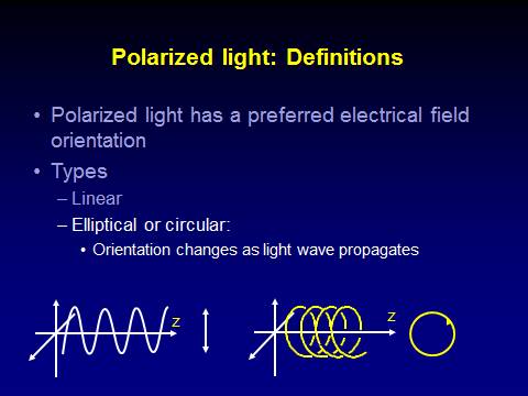
Modeling of systems that change the polarization state of light
Polarized light is widely used in optical systems for various purposes. Our retinal birefringence scanning systems measure the property of parts of the retina to change the polarization state of light, which is called “birefringence”.
The principle of
Retinal Birefringence Scanning for detecting central fixation and eye
alignment.
Polarized near-infrared light is reflected from the foveal area in a bow-tie pattern of polarization states; the pattern is similar to the faint pattern observed surrounding the point of fixation when a subject views a clear background through a polarized filter (the Haidinger brush phenomenon 6). With our previous instruments, the foveal area was probed with a circular scan of frequency f . When the eye fixated on a point at the center of the circular scan, the double-pass polarization state of the light changed at twice the frequency of the scan (2f). With paracentral fixation, the change in the polarization state was only at the frequency of the scan (f).
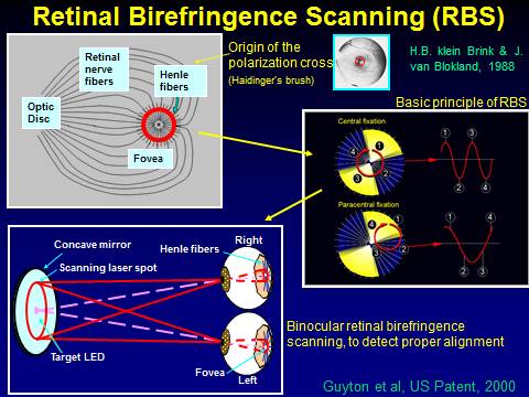
An
early version of the RBS scanner – basic principle
![]()
The full model, as presented in the illustration
below, includes also retarders (WP=wave plate; HWP=Half-Wave Plate, etc, some
of which may be rotating).
Stokes representation of the polarization state of light (Please see also the above illustration).
|
|
|
Signal strength variations for
variations in corneal and retinal azimuth and retardance
|
|
|
|
|
|
The overall bow-tie light
intensity function can be approximated with the following formula:

where q is
the azimuth relative to the fast axis of the Henle fiber birefringence, q=atan(yb/xb), and r
= (xb2+yb2)½ is the distance from the origin of the
bow-tie distribution in millimeters, on the same scale as the bow-tie image on
the surface of the photodetector. The
exponents that give the closest match to the profile shown in Fig. 6 are as
follows: τ1 = 3.7,
τ2 = 50.0, τ3
= 0.6, τ4 = 5.0,
and τ5 = 0.8. The
model uses millimeters in the detector plane (1.96 mm/degree of visual angle).
The computer model can be
used for optimizing the parameters of optical systems that use polarized light.
An example of employing the computer model for maximizing the amplitude of the
RBS signal as a function of corneal retardance and corneal azimuth is given
below, where Panels A and B represent two different designs.
References:
1.
Gramatikov
B.I., Zalloum O.H.Y., Wu Y.K., Hunter D.G.,
Guyton D.L. A Directional Eye
Fixation Sensor Using Birefringence-Based Foveal Detection. Applied
Optics, Vol. 46, Issue 10, pp. 1809-1818, April 2007,
https://www.osapublishing.org/vjbo/fulltext.cfm?uri=ao-46-10-1809&id=130944
2.
Gramatikov
B.I., Zalloum O.H.Y., Wu Y.K., Hunter D.G.,
Guyton D.L.
Birefringence-based eye fixation monitor with no moving parts.
Journal of Biomedical Optics, 2006,
11(3), May-June, pp. 034025-1 - 034025-11,
http://www.ncbi.nlm.nih.gov/pubmed/16822074
- Irsch,
K, Gramatikov, B.I., Wu, Y-K, Guyton, D.L. Improved eye-fixation
detection using polarization-modulated retinal birefringence scanning,
immune to corneal birefringence. Optics Express,
22(7):7972-7988, published on 18 March 2014,
DOI:10.1364/OE.22.007972, http://www.opticsinfobase.org/oe/abstract.cfm?uri=oe-22-7-7972
http://www.opticsinfobase.org/oe/fulltext.cfm?uri=oe-22-7-7972&id=282349
4.
Irsch,K., Gramatikov,B.I., Wu, Y. K.,
Guyton,D. L. A new pediatric vision screener employing
polarization-modulated, retinal-birefringence-scanning-based strabismus
detection and bull’s eye focus detection with an improved target system:
Opto-mechanical design and operation. Journal of Biomedical Optics, 2014, Jun 1;19(6):67004. doi: 10.1117/1.JBO.19.6.067004.
http://biomedicaloptics.spiedigitallibrary.org/article.aspx?articleid=1881172