Eye Tracking using a Retinal Birefringence Scanning (RBS) system with no moving parts and a limited number of sensors
 We previously have developed and reported an eye
fixation monitor that detects the human fovea by its radial orientation of
birefringent nerve fibers. The instrument used a four-quadrant photodetector and a normalized difference function
to check for a best match between the detector quadrants and the arms of the
bow-tie pattern of polarization states surrounding the fovea. This function had
a maximum during central fixation, but could not tell where
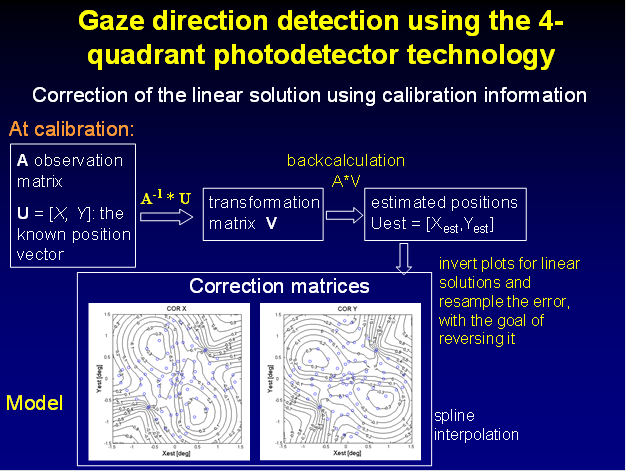
the subject was looking relative to the center. The present solution proposes a
linear transformation to obtain horizontal and vertical eye position
coordinates from the four photodetector signals, followed by correction based on a priori calibration
information. The method was verified on both a computer model, and on human
eyes. The major advantage of this new eye-tracking method is that it
uses true information coming from the fovea, rather than reflections
from other structures, to identify the direction of foveal gaze.
We previously have developed and reported an eye
fixation monitor that detects the human fovea by its radial orientation of
birefringent nerve fibers. The instrument used a four-quadrant photodetector and a normalized difference function
to check for a best match between the detector quadrants and the arms of the
bow-tie pattern of polarization states surrounding the fovea. This function had
a maximum during central fixation, but could not tell where
the subject was looking relative to the center. The present solution proposes a
linear transformation to obtain horizontal and vertical eye position
coordinates from the four photodetector signals, followed by correction based on a priori calibration
information. The method was verified on both a computer model, and on human
eyes. The major advantage of this new eye-tracking method is that it
uses true information coming from the fovea, rather than reflections
from other structures, to identify the direction of foveal gaze.
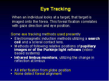
Introduction: There is an increasing demand for accurate, non-invasive eye trackers. When an individual looks at a target, that target is imaged onto the fovea. This foveal fixation correlates with gaze direction and eye position. Eye position can be estimated by a variety of techniques, each having advantages and limitations.1-9 Electromagnetic induction methods utilizing a search coil require a scleral contact lens.1, 2, 10 Other eye trackers follow relative positions of pupillary images or of the Purkinje light reflexes.3, 5, 6, 11, 12 Scleral reflection trackers require head-mounted emitters and detectors for monitoring changes in scleral reflectance induced by eye movements.7 In the last 7 years or so, the advent of CCD and CMOS cameras has led to miniaturization of video-based systems.9, 11, 12 Flying-spot scanning technologies which selectively image landmarks on the eye have improved precision, but this precision comes at the cost of interference from specular reflections, reduced speed, and limited life of the beam-steering system consisting of galvanometer-driven mirrors.8 For research purposes, most studies have used head-mounted eye-tracking devices, but more recently remote systems have been applied as well.11, 13 Some of the existing commercial systems are fast and can operate in real-time at high frame rates, such as the Chronos system (Berlin, Germany),9 the El Mar (Downsview, Ontario, Canada) eye tracker,14 and the Applied Science Laboratories (Bedford, MA) models 501 and 504.13 The most prevalent approach for gaze direction detection with most commercial systems available today appears to be the indirect method of determining corneal light reflex position versus pupil position.11, 12, 14 It seems that it has not been possible until now to detect true foveal fixation remotely, continuously, and non-invasively.
Polarized near-infrared light is reflected from the foveal area in a bow-tie pattern of polarization states similar to the Haidinger brush phenomenon.15 In the late 1980s, human foveal birefringence was measured in vivo with Mueller-matrix ellipsometry.16 In the early 1990s, the birefringence of the retinal nerve fibers was utilized by Dreher et al.17 to measure the thickness of the nerve fiber layer. Based on this, Guyton and co-authors reasoned that the birefringence of the nerve fibers surrounding the human fovea (Henle fibers) might be used to detect the strict radial geometry of the nerve fibers in the fovea. Such a technique was developed by our group, to monitor foveal fixation18-20 and to detect proper alignment of the two eyes in infants and young children21-23 for the purpose of vision screening.
Using the eye in an auto-conjugate arrangement, these instruments employed a circular scanning system. When the eye is focused in the same plane as the intended fixation point (a light source in the center of the circular scan), the light reflected from the retinal scan would be automatically focused by the eye back to the source, where it could be deflected by a beam splitter and measured for changes in polarization state induced by double passage through the Henle fibers. When the eye is looking at the intended fixation point, the circular scan is centered on the bow-tie of polarization states and the change in the detected polarization state of the light is at twice the frequency of the scan, or at 2f . With paracentral fixation, however, the change in the detected polarization state is only at the frequency of the scan f. The rapidly spinning motor, however, added noise and vibration, and was generally of limited life. To avoid these problems, we developed a no-moving-parts eye fixation monitor. Instead of circular scanning, this instrument utilizes four spots of linearly polarized light to obtain spatial information. With central fixation, two spots are aligned with the “bright” arms, and two are aligned with the “dark” arms of the bow-tie pattern of polarization states surrounding the fovea. The light reflected from the fundus travels through a quarter-wave plate, a polarizer, and onto a four-quadrant photodetector. After amplification and digitization, the signals from the four photodetectors are combined into a normalized differential signal (ND) that discriminates between central fixation and the lack thereof. At central fixation, ND reaches its global maximum, which allows it to be used in conjunction with a threshold for detecting central fixation.24 The simple ND measure can tell whether the subject is looking at the intended fixation point, but cannot provide information as to exactly where the subject is looking if not centered on the intended fixation point. To solve this problem, we propose a method for calculating the x- and y-coordinates of the point of fixation from the data received by the four-quadrant photodetector, using the same device.
System Overview and Methods
A. Instrument design and theory of operation
The instrument design has been reported in more detail in a previous paper.24 In order to obtain better symmetry of the bow-tie pattern and the light spots with respect to the photodetector, for the purpose of eye-tracking, in the present design we rotated the quadrant photodetector 45º clockwise around its center, such that the four reflected patches of light now fall on the intersections between adjacent quadrants of the photodetector. The new configuration is shown in Fig. 1. The four spots are produced from a single 780 nm, 100 mW laser diode using a multi-faceted prism. The laser is modulated by a square wave (f = 140 Hz). The intensity of light is safe for exposure times of up to 3x10⁴ seconds.25 The incident light is vertically polarized. The radially‑oriented retardance around fovea induces a circularly polarized component in the reflected beam. The light reflected from the fundus travels through a circular analyzer (quarter‑wave plate followed by linear polarizer) which produces four patches of light as parts of a bow tie intensity pattern. These spots are captured by a quadrant photodetector extending over 4º of visual angle (Centrovision QD50-0, active area 8 mm diameter). For the reader familiar with polarization optics, we measure a portion of the S3 component26, 27 of the polarization state of each reflected patch of light. In the Stokes vector representation of the polarization state, S = {S0, S1, S2, S3}, S3 represents the differential measurement of the circular polarization component (right-handed circular polarization minus left-handed circular polarization). In our device we measure the portion of the circular polarization component by first rotating the polarization states on the Poincaré sphere 90º by means of the quarter-wave plate, and then measuring the (non-differential) linear polarization along the S1 axis using a polarizer in front of the detector.
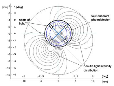
Fig. 1 An idealized 2D spatial intensity profile of the light reflected from the fundus and falling on the plane of the quadrant photodetector, if linearly polarized light were uniformly illuminating the fundus. We use only four spots of illumination, however, and the signal in each detector quadrant is calculated by integrating the intensity signal point-wise for the illuminated (rectangular) area corresponding to each spot of light.
The optical design uses a circular exit pupil of 30 mm diameter. As long as the eye is within the exit pupil, foveal position can be measured with regard to the four spots illuminating the Henle fibers. This means that the system will tolerate horizontal and vertical displacements of the eye within the exit pupil of 30 mm diameter without loss of precision, as well as forward and backward displacements of the eye of at least ±2 cm.
The four signals from the four photodetectors are amplified, filtered, and fed to a computer for analog-to-digital conversion and digital analysis. Signal processing includes band-pass digital filtering at a central frequency equal to laser modulation frequency, synchronous signal averaging, and background subtraction in each of the four channels. A background measurement, arising from lid and facial reflections, as well as from internal instrument reflections, is taken with eyes closed prior to each set of fixation measurements, and is stored separately for each channel for subsequent subtraction from the readings in that channel.
B. Computer model
We developed in MATLAB a mathematical model which helps optimize the eye-position detection algorithm.24 The graphical output of the model is shown in Fig. 1. It represents an idealized two-dimensional spatial intensity profile of the polarization-altered light reflected from the fundus, after passing through the quarter-wave plate and polarizer overlying the detector. The signal in each detector quadrant is calculated by integrating the light intensity point-wise across the area captured by each particular detector quadrant. Because this design employs four spots of light on the retina, the model uses a mask, thus sensing only light reflected by the four spots directly illuminated by the laser diode. All other parts of the retina are masked out. The spots of light are conjugate to the intersections between adjacent quadrants of the photodetector (Fig. 1), but are reflected from different areas of the fovea depending on the actual point of fixation. For simplicity, this model does not take into account the blurring which occurs due to imperfect imaging in the double pass. It rather behaves as if a four-quadrant detector were placed immediately above the retina on the return path. As reported in more detail in our previous paper,24 the bow-tie distribution of light intensities, upon passing through the polarizer overlying the quadrant detector, was modeled with a cos2(q) function where q is the azimuth of the fast axis of the Henle fiber birefringence, radially disposed with respect to the center of the bow-tie. This function was modulated with an exponentially rising and then exponentially falling radial function derived from previous measurements in our lab.28 This exponential function has a peak at approximately 1.5º of visual angle. The product of the two functions gives the bow-tie pattern shown in Fig. 1, where the two peaks are approximately 3º (6 mm in terms of detector space) apart, and represent the areas of maximum change in polarization state (S3 component measured) coming from the fovea.
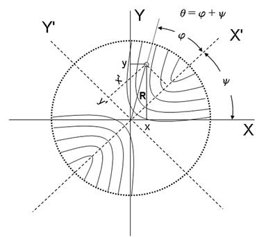
Fig. 2 The coordinate system X'-Y' of the foveal bow-tie light intensity pattern (after passing through the quarter wave plate and polarizer), as tilted at an angle y with respect to the normal Cartesian system X-Y (y » 45°).
Depending on the direction of gaze, different portions of the bow-tie intensity pattern are projected onto the four quadrants of the photodetector. In the model, the center of the bow-tie intensity pattern can be positioned at any point in the plane of the photodetector. For each position of the bow-tie center (point x,y) the model yields a set of signals [A,B,C,D] corresponding to the signals received from the four detector segments of the four-quadrant photodetector. We aligned the coordinate system X'-Y' with the axis of the foveal bow-tie light intensity pattern (Fig. 2), as tilted at an angle y with respect to the normal Cartesian system X-Y, whereby the tilt angle y could be set to an arbitrary value. In reality, the bow-tie orientation depends on the polarization properties of the incident beam, as well as on the birefringence of the cornea. For a vertically polarized incident beam, as in our system, an orientation of 45º occurs when the corneal retardance is equal to zero. The influence of the retardance and azimuth of the corneal birefringence on the orientation of the bow-tie was studied in our previous paper.24
C. The eye-tracking equation in the computer model
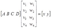
We assume that for each position of the eye there exists a set of parameters [v,w] such that
 (1)
(1)
or a V = u
where u = [x, y] is the known position vector,
a = [A,B,C,D] is the known detector output, and
V = [v,w] is an unknown transformation matrix containing 4 v-elements and 4 w-elements.
We hypothesize that, with a reasonable precision, one and the same set of transformation parameters V can be applied to the linear calculation of the coordinates of the bow-tie center (eye position with respect to the center of the four-quadrant photodetector) for all positions of the bow-tie within a certain range, and that V can be optimized such as to minimize the overall error. Further, we hypothesize that the calculation error due to deviation from this linear model can be reversed by using a priori correction information obtained after calibration, but before real-time operation.
In order to find V, the model can be used to move the center of the bow-tie intensity pattern about on a grid (g-by-h) with respect to the detector center, and the detector output ai = [Ai , Bi , Ci , Di] can be obtained for each position (observation). For all n observations ( n = g * h) we can then write the following set of simultaneous linear equations:
A V = U (2)
where A is an n-by-4 observation matrix, V is a 4-by-2 transformation matrix, and U is an n-by-2 eye-position matrix. For n>4 the matrix A is rectangular and the system is an over-determined one. Matrix A is factored using QR orthogonalization. The factors are used to solve the over-determined equations in a least squares sense. The result is a q-by-r matrix where q (q=4) is the number of columns of A , and r (r =2) is the number of columns of U. Each column of V has at most k non-zero components, where k is the effective rank of A . In our case of n-by-4, A generally has k = n (full rank). The solution for V can be given as
V = pinv (A) * U (3)
where the pinv operator finds the pseudo-inverse matrix. For solving (3) we used MATLAB. Further, in order to examine the efficiency of the computed transformation matrix V, we calculated backward uc = [x, y] as a linear solution using Eq.(1), for each of the n observations from the grid (n = g * h). The grid stretched from -1° to +1° in both x- and y-directions, and had 9 x 9 = 81 nodes (Fig. 3).
|
a |
b |
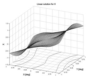
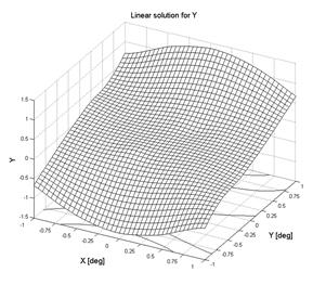
Fig. 3 Modeling eye tracking: linear solution, the back-calculated signal for X (a) and Y (b) after computing the transformation matrix V and applying it to the input data (A,B,C,D) for each point.
D. The eye-tracking equation with human data
In a similar manner we analyzed the data collected from human eyes. Four male adults, aged 23-60, were tested. The study was approved by the Institutional Review Board for all measurements described here, and written consent was obtained properly in writing from each subject. The subjects had no history of eye disease and had corrected visual acuity of 20/20 or better in the tested eye. We prepared a special 2D eccentric viewing scale for the fixation detector and reflected it via a beam splitter in the test subject’s visual field, centered on the central fixation point, in a way that allowed the subject to fixate on any intersection of the grid, at known coordinates relative to the center of the four red dots. Each measurement was background-corrected, and the average of 5 measurements was used for each point. During measurement, we recorded ai = [Ai ,Bi ,Ci ,Di] and ui = [xi ,yi] for each grid intersection, as in Eq. (1), obtaining for n nodes (grid intersections) a relationship as in Eq. (1). Then, using Eq. (3), we calculated the transformation matrix V, and calculated backward uc = [x, y] using Eq.(1), for each observation from the grid.
E. Correction of the linear solution using calibration information
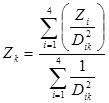
For some applications, a directional eye fixation sensor based solely on a linear solution, as given in Eq. (1), may be sufficient. For more demanding applications, we propose a correction algorithm based on correction matrices for X and Y, respectively. In this case, data acquired during calibration is used first to compute the transformation matrix V, and to calculate backward for all calibration nodes uc = [x, y] using Eq. (1), as described in Subsection 2.C and 2.D. We call these back-calculated pairs estimates of the real coordinates, i.e. xest and yest. To each pair of real coordinates [x,y] and for a given transformation matrix V, there is a corresponding pair of estimated coordinates xest and yest . Conversely, we observed in the computer model and in the human data, that no two [x,y] pairs produced the same [xest, yest] pair, or a set of pairs too close to each other. This allowed us to invert the plots for the estimated linear solutions xest and yest (Figs. 3, 6) and after resampling of the error, to present them as correction matrices (Figs 4, 7) for X and Y. Resampling was done on a regular grid using spline interpolation.29 During real-time operation, each correction matrix COR_X and COR_Y (for X or Y, respectively) is entered with the linearly estimated pair [xest, yest] and delivers the correction value for X or Y, respectively. Since entry into a correction matrix is possible only for discrete values of xest and yest , one should either use high-density matrices (finer grid cells) and approximate before entry, or, alternatively, interpolate the output value in real-time between the closest surrounding nodes (control points) of the correction matrix. We chose the second approach, to compute the output using an inverse distance-squared interpolation equation based on the values for the four corner (control) points of the matrix grid cell into which the current input falls:
![]() (4)
(4)
In this equation, Z is the final interpolated correction value for either X or Y. This method is faster and computationally simpler than the spline interpolation, while yielding satisfactory results.
Results
A. Eye tracking in the computer model
We ran the model described in Subsection 2B, with the mutual positions of the bow-tie light intensity pattern and detector being shifted by the program with a step of 0.25º in each direction (X,Y). We worked in the coordinate system X'-Y' of the foveal bow-tie light intensity pattern (Fig. 2), as tilted at an angle y= 45° with respect to the normal Cartesian system X-Y. In the rotated X'-Y' system the X'-axis runs through the middle of the areas of maximum change in polarization state (S3 component) coming from the fovea, whereas the Y'-axis halves the areas of minimum birefringence signal. The transformation from one system to another, rotated at an angle y was done using the equations:
![]() (5)
(5)
For transformations from the normal X-Y system to the foveal X'-Y' system, we used y = -45°, and for the inverse transformation X'-Y' to X-Y system, accordingly y = 45°.
The four quadrant signals A, B, C, and D were calculated for each position in X'-Y' and used for computing the transformation matrix V according to Eqs. (2) and (3). Here the known position vector u of Eq. (1) is in the foveal bow-tie coordinate system. Then the values for X' and Y' were back-calculated, returned to the original normal coordinate X-Y system (Eq. (5), y = 45°), and plotted for each position after interpolation on a finer grid (Fig. 3).
For the whole field studied, it can be seen for the simple linear solution that the X-measure gradually increases from left to right on the X-plots [Fig. 3 (a)], and the Y-measure similarly increases from down to up on the Y-plots [Fig. 3(b)]. There is also a central area of approximately 1.0º x 1.0º where the coordinates returned by the linear calculation closely match the original offsets and change nearly linearly with them, in both the x- and y-directions. Yet, outside the central region, the error increases significantly. The correction matrices COR_X [Fig. 4(a)] and COR_Y [Fig. 4(b)] improve precision, rendering the corrected x and y excellent linear functions of the original direction of gaze [x, y] (Fig. 5). The absolute error after matrix-based correction does not exceed 0.03º for either X or Y , which is 1.5% of the size of the whole field studied.
|
a |
b |
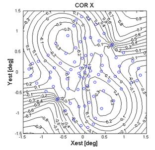
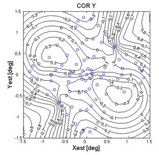
Fig. 4 Modeling eye tracking: resampled correction matrices for X (a) and Y (b). The circles indicate data coming from nodes on the original grid.
|
a |
b |
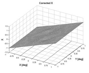
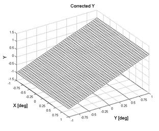
Fig. 5 Modeling eye tracking: the corrected signals for X (a) and Y (b) after XY matrix correction.
B. Eye tracking in human subjects
Using the technique described under 2.D, we collected data from the right eyes of three properly consented human subjects, using a 2D eccentric viewing scale. Concordant with the results in Subsection 3.A, data were obtained from the central area of 2º x 2º, in the range [-1.0°…+1.0°] for both the x and y directions. As in 3.A, the coordinates were first converted to the coordinate system X'-Y' of the foveal bow-tie light intensity pattern. Then, based on the known position vector u = [x, y] used for fixation when collecting data from different spots on the eccentric scale, for each subject the transformation matrix V was calculated [Eq. (3)], and for each observation the predicted position vector uc = [x,y] was back-calculated [Eqs. (1,2)]. Finally, computed coordinates were returned to the original X-Y coordinate system [Eq. (5), y = 45°]. The results for X and Y for one of the subjects are presented in Fig. 6.
|
a |
b |
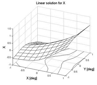
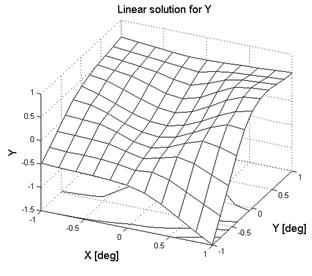
Fig. 6 Eye tracking with human data: linear solution, the back-calculated signal for X (a) and Y (b) after computing the transformation matrix V and applying it to the input data (A,B,C,D) for each point.
For the linear solution applied to different points on the field studied, it can be seen on the plots for X [Fig.6(a)] that the x-function increases monotonously from left to right, although this rise is not the same for different values of Y. Similarly, the plots for Y [Fig.6(b)] show a function generally proportional to the y-coordinate, but the rate of increase depends on the x-position. Although the functions for X and Y are monotonous, linearity exists only in the central region and deteriorates toward the corners of the field studied. The linear error for X can be as high as 0.7º which is 35% of the field size, and the error for Y can reach 0.5º, equivalent to 25% of the field size in the border areas. Such precision may be good only for very unchallenging applications (like actuating of big visual “buttons”), but is obviously insufficient for more demanding tasks. The correction matrices COR_X [Fig. 7(a)] and COR_Y [Fig. 7(b)] improve precision considerably, resulting ultimately, as with the model, in very good linear behavior of both X and Y [Fig.8 (a,b)]. The absolute error after matrix-based correction amounts to less than 0.09º for X and less than 0.05º for Y , which are 4.5% and 2.5% of the size of the whole field, respectively.
|
a |
b |
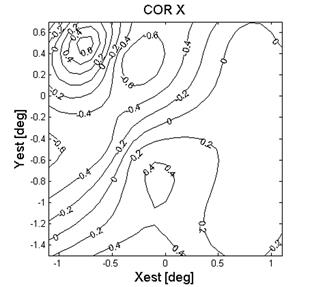
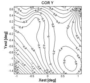
Fig. 7 Eye tracking with human data: resampled correction matrices for X (a) and Y (b)
|
a |
b |
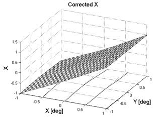
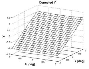
Fig. 8 Eye tracking with human data: the corrected signals for X (a) and Y (b) after XY matrix correction.
All four tested subjects performed similarly, with the error not exceeding 0.11º for X and 0.08º for Y (5.5% and 4.0% relative to the field size, respectively).
Discussion
The major advantage of this eye-tracking method is that it uses true information coming from the fovea, rather than reflections from other structures, to identify the direction of foveal gaze. We believe that a sensor based on true foveal fixation, despite all the difficulties described in this article, would be superior to common commercial eye-trackers employing the corneal light reflex and/or pupil information. Other currently used methods are either invasive, restrict head movement strongly, or provide output referenced to head coordinates only. In most studies of eye position, it is the projection of the fovea onto the environment (fixation) that is of interest. Our method can detect true foveal position. Most other techniques measure the orientation of the globe (eye position), requiring a calibration step to avoid discrepancy between inferred and true foveal fixation in certain eye conditions (e.g. eccentric pupil). The present measuring principle, although requiring calibration too, is based on auto-conjugacy of the retina with the light source and with the detector and permits relatively free movement of the head. 19
The eye-tracking range can significantly be increased by using the retinal nerve fiber layer (RNFL) which creates a similar bow-tie pattern of polarization states around the optic disc in polarized light reflected from the fundus. The RNLF pattern spans about 20º, compared to the 5-6º covered by the Henle fibers surrounding the fovea and used in the present device.
A substantial difficulty with the implementation of the method used in the present study is the low signal-to-noise ratio of roughly 0.1 due to light reflected from the lids, sclera, and cornea. This problem was largely solved by using time-synchronous averaging of a number of measurement cycles. Increasing the number of averaged cycles with the purpose of achieving more stable readings would limit even further the time resolution of the directional eye fixation sensor. Clearly, increasing the signal-to-noise ratio is necessary. This could be achieved by masking the face and sclera with a low-reflective material such as black felt. Such a mask in our tests decreased the background signal from facial reflections about three-fold and greatly improved measurement stability of the eye tracker. Another way to reduce the effect of the reflections from the sclera, cornea, and face would be to modify the system such that the four light spots are fired sequentially, rather than simultaneously – i.e. by using four truly separate laser point sources instead of one laser diode with a multi-faceted prism. This would decrease background noise nearly 4 times, and reduce the number of cycles needed to be acquired and averaged. Indeed, a rapidly fired array of 8 or 16 light spots would simulate a scanning motion and provide the noise-reduction advantages of a scanned system without need for moving parts, perhaps eliminating the need for signal averaging.
Head tilts and ocular torsion appearing after calibration would produce artifacts that our device is not designed to accommodate. Future work aimed at calibration at different tilt angles and estimating a change of angle y in real-time may solve this problem. Possible media opacities, such as corneal scars or partial cataracts, would also adversely influence precision.
Another factor that potentially may deteriorate the precision of this device is small pupil size. Since the eye tracker uses a double pass method, pupil constriction after calculation of V and the correction matrices may play a negative role in the precision of eye-position detection. We have successfully tested the device in a low-light environment only. The impact of changing the level of the room lights has yet to be studied. Yet again, some existing eye-tracking systems were reported to be used in laboratories lit dimly.11, 14 Systems employing an infrared source of eye illumination usually perform much better at low ambient light levels. However, accommodation also induces pupil constriction, and accommodation may occur during visual demanding tasks that might require eye tracking.
Conclusion: In summary, this work demonstrates the feasibility of an eye tracker that utilizes birefringence-based foveal position detection. Our method and device can be used for remote, non-invasive, continuous monitoring of foveal fixation within ±1° in both the horizontal and vertical directions, at a relatively slow speed. The field can potentially be expanded by using other birefringence structures of the fundus of the eye such as the retinal nerve fiber layer around the optic disc. We believe that reading rates of several hundred measurements per second are achievable with this method. The approach has potential use in vision diagnostics, remote control applications, security systems, aids for disabled people, biometrics, vehicular technologies, computer gaming, and other areas. It requires no rigid head fixation and needs no head-mounted appliances.
Acknowledgments: This work was supported by awards from Research to Prevent Blindness and the Alcon Research Institute, and by NIH Grant EY12883. Mr. David Kays from the Wilmer Eye Institute provided technical assistance.
References
This material is covered in more detail in the following publication:
1. Gramatikov BI, Zalloum OHY, Wu Y-K, Hunter DG, Guyton DL. A directional eye fixation sensor using birefringence-based foveal detection. Applied Optics. 2007; 46(10):1809-1818,
https://www.osapublishing.org/vjbo/fulltext.cfm?uri=ao-46-10-1809&id=130944